
Sponsored by TTI.
Whether for the BMS or motor control, here are the key specs to understand when
sourcing these critical EV components.
Electric vehicles continue to grow in popularity and market share, and electric current is the fuel of the future. Current sensors are a critical component of today’s EVs, serving two primary applications according to Ajibola Fowowe, global offering manager at Honeywell.
“The battery management system (BMS) uses current sensors, in conjunction with other sensors such as the voltage and temperature sensors, to monitor the state of charge and overall health of the battery pack. The other use for current sensors is in motor control, where it is relied on to quickly detect and isolate a fault in the electric drive,” said Fowowe.
Regardless of the use case, there are several considerations EV engineers must understand when selecting among the many available current sensors. Here’s what you need to know.
Types of EV current sensors
There are different types of current sensors that each have advantages and disadvantages for EV applications.
Closed loop current sensors
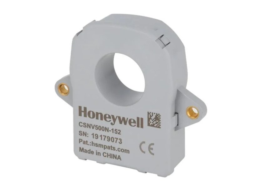
Closed loop current sensors have a feedback system for improved measurement accuracy. A magnetic core concentrates the magnetic field generated by the flow of current and provides a proportional voltage to the amount of current detected in the core. This enables the sensor to generate a precise current measurement. Because of their high accuracy and stability, closed loop sensors are well suited for use in the BMS.
The Honeywell CSNV 500 (pictured above) is a closed loop current sensor rated for a primary current measurement range of ±500 amps of direct current. The CSNV 500 features a proprietary Honeywell temperature compensation algorithm with digital CAN output, to provide high accuracy readings within ±0.5% error over the temperature range of -40⁰ to 85⁰ C for robust system performance and reliability.
Open loop current sensors
Open loop current sensors operate on the principle of magnetic induction. They consist of a primary winding, through which the current travels, and a secondary winding that measures the induced voltage. Open loop sensors require less additional electronics and processing compared to closed loop sensors, resulting in faster response times. However, they require additional calibration because they are more prone to variations in heat and magnetic field. This means they are also less accurate — reaching approximately 2% error of the primary readings.
The fast response time of open loop current sensors makes them ideal for motor control functions. Motor control applications don’t require the same level of precision as the BMS, so the loss of accuracy compared to a closed loop or flux gate sensor isn’t critical.
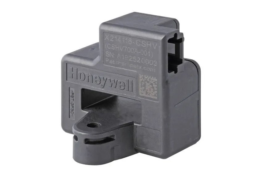
The Honeywell CSHV line of open loop sensors have a range of 100 amps to 1,500 amps, and their response times are as fast as six microseconds. They are used in fault isolation and fault detection, as well as controlling motor speed. They can also be used in battery management systems that do not require very high accuracy, such as in hybrid electric vehicles. These sensors use AEC-Q100 qualified integrated circuits to meet high quality and reliability requirements.
The Honeywell CSHV series open loop sensor
Honeywell’s CSNV 1500 has both closed loop and open loop functionality. This enables the sensor to meet an accuracy requirement of 1%, and is designed for applications that require high accuracy. The CSNV 1500 is used for similar EV applications as the CSNV 500, as well as stationary energy storage systems and industrial operations.
Flux gate current sensors
Flux gate current sensors measure changes in the magnetic flux of a current as it passes through a magnetic loop, from which it can derive current measurements. The Honeywell CSNV 700 is designed for applications that fall between 500 A and 1,000 A requirements. It has a better zero-offset and higher sensing range than 500 amps sensors—but it also has higher power consumption than a closed loop sensor. The CSNV 700 has similar accuracy rating as the CSNV 500, at 0.5%, and it also uses AEC-Q100 qualified integrated circuits.
As with closed loop sensors, the flux gate sensor is best used in BMS settings that require high accuracy. When using flux gate sensors, however, engineers need to be mindful of their higher power requirements, which could consume more battery energy.
Honeywell’s CSSV 1500 is a combination open loop and flux gate sensor. It was designed to meet Automotive Safety Integrity Level C (ASIL-C) requirements for safety-critical applications where customers desire a higher level of reliability and performance. While many 1500 A sensors consume more power, the combination of open loop and flux gate technologies uses less power while still meeting the accuracy and functional safety requirements. It meets Automotive Safety Integrity Level C (ASIL C) requirements for safety critical applications. This requirement is typical of battery electric vehicles (BEV).
Shunt current sensors
A shunt current sensor measures the voltage drop across a sense resistor placed in the conduction path between a power source and a load. It is an inline current sensor connected directly to the busbar; closed loop, open loop and flux gate sensors are non-contact sensors that don’t have that direct connection.
One of the benefits of a shunt sensor is that it can provide an instantaneous measurement of current. However, it generates more heat and contributes to power loss in the circuit. This creates parasitic energy waste. Fowowe says that advancements in shunt technology is increasing its attractiveness in high voltage systems and Honeywell is actively researching additional value that can be derived from the application of shunt technology such as the potential combination of current and voltage measurements into one sensor to reduce the overall cost of the BMS.
Other key considerations for EV current sensors
In addition to considering which sensor to use in which application, engineers will also need to factor in other variables. Since the sensor needs to work properly in a magnetized environment, its capacity to handle magnetic interference is important. For BMS applications that rely on a high level of accuracy, engineers will need to consider the sensor’s zero-offset, which is the amount of deviation in output or reading from the lowest end of the measurement range.
Ease of integration is also important to consider. EVs can use either controller area network (CAN bus) standard or analog outputs. CAN communication is more common in the BMS. CAN bus communication speed is limited by the CAN protocol to 10 milliseconds, which is acceptable for the BMS. For more immediate measurements, motor control functions use analog outputs, which can respond in microseconds.
Another factor to be mindful of is the EV’s driving environment. EVs need to be able to function properly in any conditions, from a heat wave in Arizona to a snowstorm in New York. Therefore, the sensor’s operating temperature range needs to be factored in. According to Fowowe, Honeywell’s sensors are built to maintain performance in temperatures ranging from -40 to 85 degrees Celsius; the sensors feature a Honeywell patented multi-point temperature compensation algorithm to ensure the sensors can deliver very high accuracy and performance under any driving condition.
To learn more about current sensors for EVs, visit Honeywell at TTI.

Source link by Charged EVs
Author Charged EVs
#engineers #current #sensors #applications


